Today’s Whimsy
My Elmer had a rig with an Eddystone dial
And was often at the bottom of a DX pile.
A new tall beam
Perfected his scheme,
And contacts aplenty filled his QSL file.
EFHW, The End Fed Half Wave
The end fed halfwave is currently a very popular antenna, especially for portable operation. I modestly claim to have been an early fan who praised the form in an April, 1989 article in QRP Quarterly. For HF operation, it offers low ground losses. In an inverted L configuration, just hook one end directly to your impedance matcher, and go to work. On VHF, the familiar J pole is another example.
At one time, an end fed halfwave was my VHF mobile antenna. I cut down a hard plastic drinking glass, mounted an SO239 connector on what had been the base, made a little matching section inside the glass, and glued a round magnet on its mouth. A 2 meter halfwave plugged into the connector, and it performed admirably. I was seriously annoyed when someone stole it, leaving a shredded stump of coax.
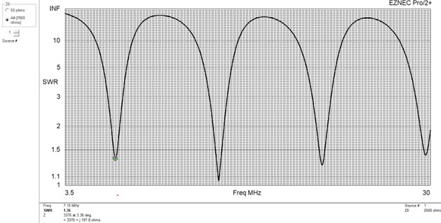
With a center fed halfwave, you get resonances at the fundamental frequency, plus extras at 3X and 5X (and other odd multiples of) the fundamental. If you end feed a halfwave, you get additional resonances at 2X and 4X (and other even multiples). Here is an SWR plot of a 40 meter end fed halfwave, if matched to 2500 ohms. The first resonance is at 7.15 MHz, the second at 14.65, the third at 22.15, and the fourth at 29.65. The higher resonances are close enough to the ham bands that a little fiddling with antenna length will bring a good match.
One prevailing implementation is to use a 1:49 transformer for the impedance match. This is a very compact solution, but it does have a problem: It’s hard to get more than about 90% efficiency, especially across a large piece of the HF spectrum. Nobody on the other end is going to miss half a dB of signal strength. But if you’re running 100 watts, the transformer has to dissipate 10 watts. That can be an issue. Of course, if you’re running QRP, it’s probably not.
My preferred HF solution is to make the antenna just a little longer than an electrical halfwave, to avoid hitting right on the highest impedance point, and to match it with a small tuner. Tuners are not 100% efficient, either, but with air core inductors, I have yet to detect any heating in mine. The transmitter is connected to the tuner with a short piece of coax, and the end of the inverted L is brought directly to the tuner. This arrangement still minimizes ground currents, so losses there can be small. And it does not require fiddling with antenna length to get a good match.
So do you even need a ground? I think so, even though a common practice is to NOT use ferrite beads on the coax and to forgo a dedicated RF ground. This makes the outer surface of your coax shield and your transmitter chassis the ground. That seems a bit sporting to me, but to each his own.
My test for adequate ground was to put a hand on the tuner, to see if my body capacitance would change the SWR. It did. With a high impedance feed point, four ¼ wave radials are plenty, and that change eliminated the SWR shift. At the time, I was working at Tektronix, and got to associate with some pretty high powered RF folks. Their consensus was that the body capacitance test was actually a very good test for sufficient ground in this particular case.
I also add Type 31 ferrite beads to the coax, to keep it from trying to be a radial.
What’s not to like? It’s simple and effective. In most cases, it’s mechanically easier than a center fed arrangement. And you get more resonances for your money.
73 for now,
Denton
W7DB